Date: 2026.08.18 Click: 2
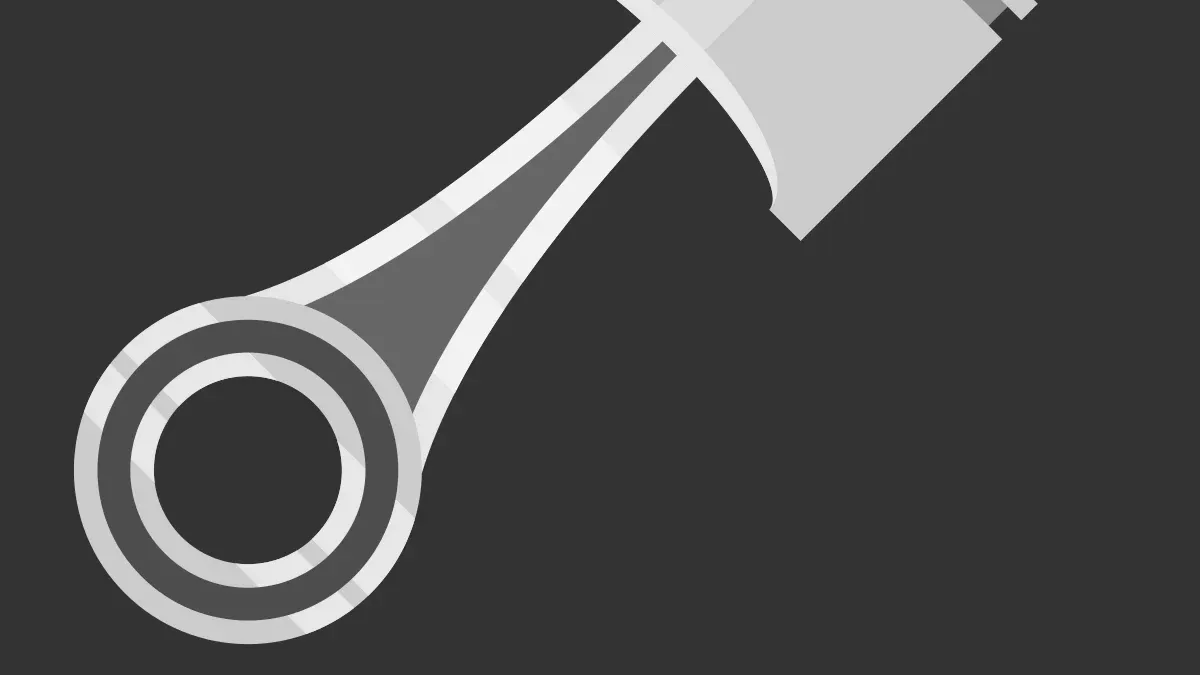
A connecting rod works as a strong metal link that joins the piston to the crankshaft inside your engine. You depend on this important part to turn the up-and-down straight movement of the piston into spinning power at the crank journal. During the power stroke, burning fuel builds up strong pressure from the explosion. This pushing force moves the piston down fast. The rod takes in this strong push through its small top pin, acting just like a simple lever. It passes the heavy load down to the large bottom bearing that wraps around the crankpin. This movement creates the turning force that your car needs to run. The part faces constant pushing and pulling forces during every single engine stroke.
Key TakeawaysConnecting rods turn the piston's up-and-down motion into the engine's rotating power.
I-beam and H-beam designs handle different pushing and stretching forces inside the engine.
Forged steel rods provide the best strength for high-speed driving.
Deep knocking noises and low oil pressure show that your rod bearings are badly damaged.
Changing your oil often protects engine bearings from wearing out early and breaking expensively.
You rely on the core drive system to power your vehicle smoothly. This primary engine drive system combines three essential parts into a single slider-crank setup: the piston, the connecting rod, and the crankshaft. These individual parts must work in total harmony to change energy and send power to your drivetrain without failing.
|
Component |
Role in core drive system |
Interaction with other parts |
|---|---|---|
|
Piston |
Holds back explosion pressure |
Drives the rod down the cylinder wall |
|
Connecting rod |
Sends straight pushing force |
Links piston wrist pin to crank journal |
|
Crankshaft |
Changes movement into spinning power |
Takes in rod force and spins the flywheel |
Your engine turns burning fuel into car movement through continuous mechanical steps. You can follow this power path during the normal four-stroke cycle:
Burning fuel forces the piston downward inside the cylinder bore during the power stroke.
The small end attached to the wrist pin directly follows this straight piston movement.
The strong main beam passes this motion energy down to the big end.
The big end pushes the offset crank arm to turn the main crankshaft.
Engine makers must balance strong part strength and light moving weight during this mechanical process. A high-performance car engine needs a total rod weight below 400 g to lower fast-moving forces. These forces grow rapidly as engine speed goes up. Doubling your engine speed multiplies these mechanical forces by four times. Engine builders aim for a peak pull stress between 400–600 MPa and keep a safety buffer of 2.5–3.0 under heavy work conditions. They also design for a target rod-length-to-stroke ratio between 1.65–1.75. Ratios below 1.5 angle the beam sharply at mid-stroke, which pushes the piston harder against the cylinder wall and speeds up side wear. Ratios above 2.0 need taller engine blocks and add extra useless weight.
Your internal combustion engine puts inside parts under constant pushing and pulling forces. Burning fuel creates huge crushing forces that push down on the beam during the power stroke. Heavy H-beam shapes resist these strong bending forces very well. On the other hand, piston weight pulls the parts upward in pure tension at top dead center during the exhaust stroke. Light I-beam shapes handle these stretching forces easily. Stretch forces on the parts reach 27.6 kN at 8,500 RPM and grow to 34.5 kN at 9,500 RPM.
|
Engine speed |
Tensile load per rod bolt |
Context and load condition |
|---|---|---|
|
800 RPM |
143 N |
Normal engine idle speed |
|
7,500 RPM |
12,540 N |
Normal track racing speed |
|
9,200 RPM |
18,870 N |
Highest engine speed limit |
Exact weight matching across all cylinder parts stops harmful engine shaking:
Weight changes create uneven forces that grow quickly as the engine spins faster.
Tiny weight differences create strong shaking forces over 500 N at speeds above 6000 RPM.
Toyota matches part sets in twin pairs within 0.5 g to stop wobble forces.
ZF groups single parts into weight sets with under 1 g total weight difference.
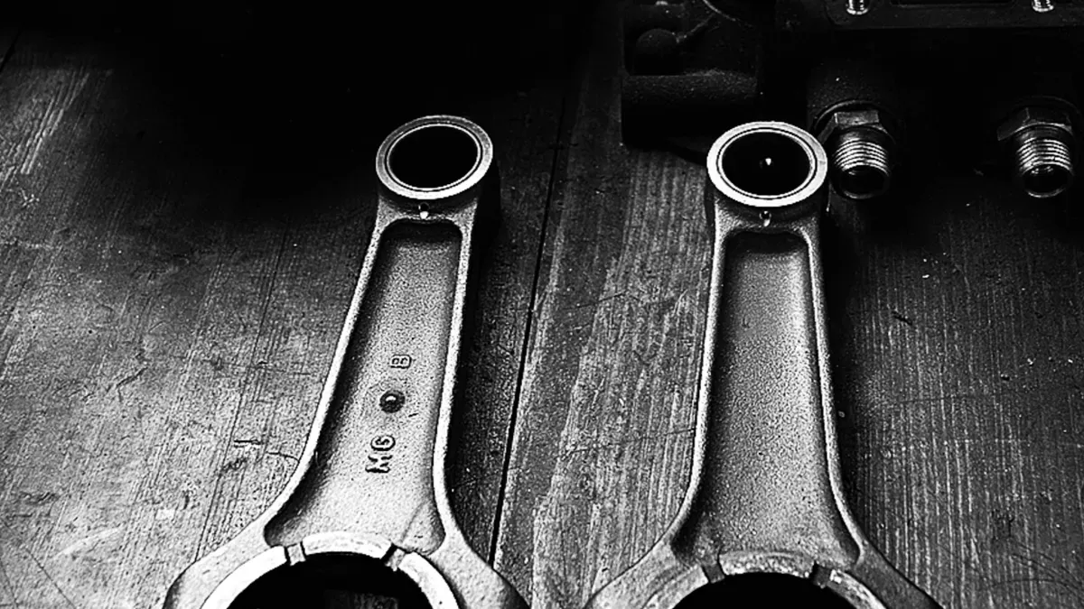
Engine builders pick special beam shapes to control different strength levels inside your motor. Most high-power engines pushing past 1000 hp use I-beam styles for better support. The cross-section looks just like a big "I" with extra metal along the middle. This thick middle part helps the piece stand up against huge crushing forces during high-boost driving.
H-beam options feature a cross-section shaped like a big "H" to reduce pulling stress. Designers usually taper this beam style so they can trim extra weight near the piston top. You can pick H-beam options for non-turbo or high-speed race engines. The light body lowers piston strain and helps your engine rev up very quickly.
Making methods directly control how much force your engine parts can handle. Factory cast iron uses metal shapes pressed into sand molds to lower building costs. Sadly, tiny air pockets inside can shorten the overall working life of cast pieces. Powdered metal parts start as iron powder mixed together with copper, nickel, and carbon. Strong machines squeeze this loose powder under big pressure. Special ovens bake the piece at 1100–1150°C to hit a solid density of 7.3–7.5 g/cm³. Extra double-press steps can push that solid density up to 7.6 g/cm³. Most basic passenger cars up to 150 horsepower use these powdered metal pieces.
High-power engines must use forged steel or special custom billet options. Forged pieces start as hot steel blocks squished inside tight metal molds. This extreme pressure makes a tough inner structure with smooth flow lines running straight through. Billet pieces are carved out of single metal blocks for perfect balance and light spinning weight. You can pick aluminum, titanium, or super-light blended materials for extreme race cars. A forged connecting rod offers the absolute best strength against bending under huge commercial loads.
Diagnosing Connecting Rod Failure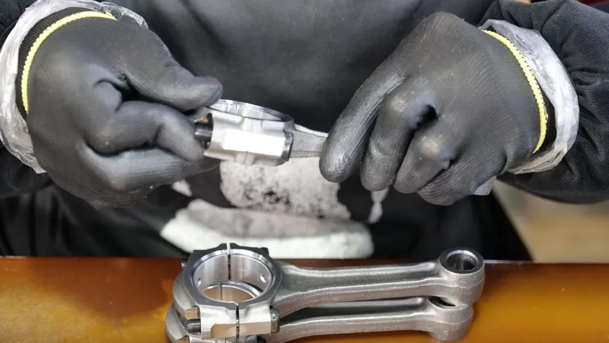
Listening closely to engine sounds helps you spot mechanical trouble very early. Old, worn internal parts create a clear knocking noise that speeds up with the engine. At a steady speed, you will hear a light, even tapping sound coming from deep inside the crankcase. Pushing the gas pedal under heavy loads changes this soft sound into a much sharper, clearer metallic thud. Slowing down is actually not the best time to listen for this specific knocking noise. Fixing these odd engine sounds quickly prevents much bigger problems later.
Bad bearings also cause engine oil pressure to drop without warning. Extra space between worn parts lets pressurized oil spill out fast from around the main crank journals. Increased rubbing inside the cylinder lowers your engine power, and worn bearing surfaces shed tiny metal bits straight into the oil. Ignoring these warning signs can cause the engine to freeze up completely when moving parts lock together.
Testing your engine oil regularly helps you catch internal wear before a rod breaks completely. Special lab tests can find microscopic metal pieces trapped inside your dirty motor oil.
|
Indicator |
Wear Interpretation |
|---|---|
|
Lead (Pb) |
Shows initial bearing overlay wear |
|
Tin (Sn) |
Confirms degradation of the overlay shell |
|
Copper (Cu) |
Reveals deep bronze backing exposure |
Higher lead and tin levels mean the outer bearing layer is wearing away. Seeing copper next shows that wear has reached the inner bronze layer beneath. Finding these metals together proves that your connecting rod bearings are wearing out fast inside the motor.
Changing your motor oil on time keeps the oil thick enough to protect your internal engine parts. Good oil thickness stops metal from rubbing against metal and prevents severe bearing damage. Mechanics use four easy checks to test for wear before severe damage happens:
|
Diagnostic test |
Indication of wear |
|---|---|
|
Listening check |
Detects knocking rhythms tied to speed |
|
Pressure gauge |
Shows low oil pressure at idle |
|
Filter examination |
Finds trapped metal fragments |
|
Plastigage clearance |
Measures exact bearing clearance gaps |
Each connecting rod helps move power and keep your engine strong. These main parts take on heavy pushing and pulling forces during every single stroke.
|
Engine Aspect |
Key Factor for Durability |
|---|---|
|
Structural Function |
Handles 200 million heavy force cycles |
|
Material Choice |
Tough forged steel and powder metals add strength |
|
Maintenance Focus |
Correct oil gaps lower early bearing wear |
Using tough forged steel or powder metals helps the parts resist breaking over time. Exact weight matching stops harmful shaking when the engine spins very fast. Also, good oil flow and tight bolts keep the inner surfaces safe from quick damage. You should change your oil regularly to protect bearing life and save your engine.
FAQA broken connecting rod causes massive damage inside your motor. The loose metal piece punches straight through the engine block or bends your valves right away. Your car loses all power on the spot, so you must rebuild the whole motor or replace it entirely.
Mechanics tell you never to change just one rod in your engine. A single replacement piece has a different weight than your old factory parts. You need to put a balanced set in every cylinder to avoid bad motor vibrations and fast bearing wear when driving fast.
Huge pressure from trapped water or bad engine knocking bends the main beam. Revving the motor too fast stretches the part past its limit. Also, running low on oil creates hot friction, which locks the bearing and snaps the rod when pushing hard.
Forged rods begin as hot steel blocks pressed super hard to make a strong inner structure. Cast rods use liquid metal poured in molds, which leaves small air bubbles behind. Because of this, forged options handle much bigger crushing forces during high-speed driving.
Please leave your requirements and contact information, and we will send you the quotation information as soon as possible.