Date: 2026.08.17 Click: 6
To choose the right performance camshaft, you must match your engine's RPM range to your vehicle weight, gear ratios, compression, and transmission setup. The intake duration directly controls whether you get low-speed pulling power or high-speed horsepower for your needs.
|
Camshaft type |
Advertised duration |
Typical operating RPM range |
Observed effect |
|---|---|---|---|
|
Factory/street cam |
Shorter duration |
1,500–5,000 RPM |
Better low-speed torque, quick gas pedal response, smooth idling |
|
High-performance aftermarket cam |
Longer/wider duration |
6,000–8,500 RPM |
More high-speed power and top pulling strength; weaker low-speed torque |
You must pick valvetrain parts based on easy driving and how well everything works together. Smart car owners never pick an engine setup just to get a rough, noisy idle sound.
Key TakeawaysChoose your performance camshaft based on your complete engine build and daily driving goals.
Look at camshaft duration specs at 0.050 inches of lift to compare different brands fairly.
Multiply the lobe lift by your rocker arm ratio to calculate the total valve lift.
Match your engine's main power range to the right rear axle gears and the total weight of your car.
Add 500 RPM to the camshaft starting speed to set automatic converter stall points.
Use high-zinc break-in oil above 2,000 RPM to protect new flat-tappet components.
Keep enough safe space between the valves and pistons to avoid destroying the inside of your engine.
Do not use a camshaft that is too large for your engine, which helps keep low-speed power and smooth daily driving.
You must understand valvetrain details to build a powerful engine. Makers measure shapes differently, so you need to know which numbers truly count. Selecting the right camshaft guarantees complete reliability.
Advertised duration measures the total time a valve remains off its seat. Toolmakers use various starting points for this exact test. Because of this, advertised numbers make matching different brands very tricky. You should check duration at 0.050 inch tappet lift instead. This standard measurement gives you a fair match between designs.
Duration decides where your engine produces its power.
Shorter duration at 0.050 inch lift raises low-RPM strength for street driving, towing, and stock cars.
Longer duration at 0.050 inch lift pushes power higher up the engine speed range for fast racing.
Brief profiles improve gas pedal feel at much lower engine speeds.
Extended profiles maximize high-RPM airflow but sacrifice low-end power.
Lobe lift shows the tallness of the lobe on the shaft. You multiply lobe lift by your rocker arm ratio to find complete valve lift: valve lift = lobe lift × rocker ratio. As an example, a 0.350-inch lobe lift with 1.5:1 rockers makes 0.525-inch valve lift. Changing to 1.65:1 rockers boosts total valve lift to 0.577 inches.
|
Lobe lift (in) |
Rocker ratio |
Valve lift (in) |
Why it matters |
|---|---|---|---|
|
0.300 |
1.5:1 |
0.450 |
Standard small-block Chevy |
|
0.333 |
1.5:1 |
0.500 |
Base lift with a camshaft profile |
|
0.333 |
1.6:1 |
0.533 |
Bigger ratio boosts lift to grab extra head airflow |
|
0.333 |
1.7:1 |
0.566 |
Extra lift, but brings more valve speed and float danger |
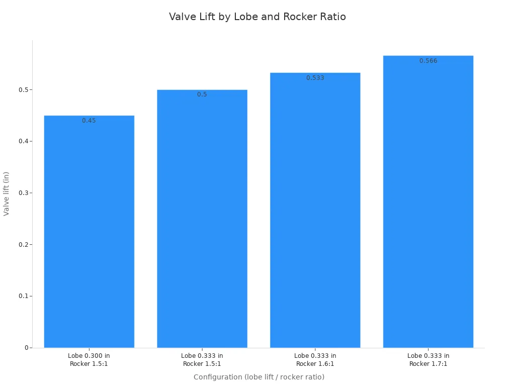
Taller valve lift allows your cylinder heads to push much more air. Faster-opening shapes deliver stronger power response within your chosen engine speed range. Still, cylinder head ports can hit maximum airflow limits. Extra lift past head limits adds parts stress without yielding any extra power.
Lobe separation angle measures the space between intake and exhaust lobe centers. Tight angles from 106 to 108 degrees raise valve overlap and move peak torque lower. Wide angles from 112 to 116 degrees cut overlap for cleaner engine running on normal roads.
Valve overlap happens when intake and exhaust valves stay open together. Narrow angles drop your engine vacuum at a 1,000 rpm idle speed. This produces a chopped idle sound. Wide angles keep solid engine vacuum for power brakes and easy driving.
Matching Profile to Vehicle and Engine BuildDynamic compression begins only when the intake valve closes completely. The intake valve closing point after bottom dead center determines how far the piston rises before air compression starts. Later closing leaves less remaining stroke for trapping air inside the cylinder during engine operation. A 3.750-inch stroke engine with the piston already 1 inch up when the intake valve closes retains only 2.750 inches of dynamic compression stroke. Dynamic compression ratio calculations use swept volume versus chamber volume without factoring volumetric efficiency. You must account for stroke length and rod dimensions when calculating your total engine compression.
Later intake valve closing reduces dynamic compression ratio and lowers overall cranking cylinder pressure.
Earlier intake closing raises trapped cylinder pressure and improves low-speed torque delivery for street driving.
Piston position changes based on connecting rod length and overall engine stroke specifications.
A 10:1 static-compression engine with a 3.48-inch stroke, 6-inch rods, and intake closing at 90 degrees ABDC acts like 6.17:1 dynamic compression.
You must raise static compression to 13.2:1 to reach an 8.0:1 dynamic compression ratio with that exact 90-degree intake closing point.
Dynamic compression directly influences your engine octane requirements and spark timing stability. Measured cranking cylinder pressure often strays from basic theoretical calculations because airflow speed and cylinder filling change real pressure values. An engine with an 8.5 dynamic compression ratio was predicted to crank below 125 psi, but a physical test gauge registered 155 psi. Advancing your valve timing closes the intake valve earlier, which elevates cylinder pressure. Choosing a high performance camshaft profile changes these trapped cylinder pressures significantly. Higher cylinder pressures require higher octane fuel to prevent destructive spark knock. You must balance your spark curve to protect your engine under heavy load.
Heavy vehicles require adequate torque low in the engine speed range to move from a dead stop. Automatic transmission vehicles require a matched torque converter to keep the engine inside its efficient operating window.
Rule of thumb: Take the starting RPM of the camshaft’s powerband and add 500 RPM to get a stall-speed starting point. For a performance camshaft with a 2,500–6,500 RPM operating range, this gives 3,000 RPM as the recommended stall-speed starting point for automatic-transmission vehicles.
Installing a torque converter with a lower stall rating bogs the engine down during sudden acceleration. Matching your torque converter rating to your chosen camshaft profile ensures smooth street performance without excess heat buildup inside your transmission.
Your rear axle gear ratio must complement your active powerband. Deep gear ratios help accelerate heavy vehicles by multiplying engine torque. Taller gear ratios drop highway engine speeds, but they can trap your engine below its optimal power band. You must select gear ratios that align cruising speed with the lower edge of your valve timing profile. Proper gearing prevents engine lugging and preserves throttle response across all driving conditions. The right gear choice keeps your camshaft operating inside its optimal speed window.
Your valve lift profile must match the airflow capability of your cylinder heads. Flow benches measure how much air volume passes through intake ports at designated valve positions.
|
Valve lift (in) |
Intake flow (cfm) |
|---|---|
|
0.600 |
248 |
|
0.650 |
249 |
Stock 799 cylinder heads deliver 248 cfm at 0.600-inch lift and reach 249 cfm at 0.650-inch lift. Aftermarket cylinder heads must exceed these stock flow numbers to reach higher output targets.
A flow benchmark of 260+ cfm supports 500 horsepower in naturally aspirated V8 applications.
Pushing valve lift beyond head port limits increases valvetrain wear without producing extra power.
Selecting appropriate valve lift ensures high flow efficiency across the entire engine speed range.
Intake manifold design affects how air moves into your cylinder heads. Intake runner length shifts peak engine tuning frequency across different speed ranges. Long intake runners build high velocity at lower engine speeds to boost low-end pulling power. Short intake runners allow high engine speeds to draw large volumes of air without restriction. High-output engines targeting 500 horsepower benefit from short-runner intake designs like LT1, Mini Ram, or Stealth Ram manifolds rather than long-runner intake setups. Synchronizing your manifold runners with your camshaft specifications ensures maximum volumetric efficiency and strong engine response.
Evaluating Camshaft Designs by Application
Selecting engine parts requires matching mechanical designs to vehicle goals. Engine builders choose different valvetrain styles based on power output, budget limits, and operating stress.
Hydraulic lifters use internal oil pressure to eliminate clearance gaps automatically. They cushion valvetrain action and eliminate routine manual valve adjustments. Solid lifters demand precise mechanical lash settings with feeler gauges during initial assembly and regular maintenance. Solid lifters maintain precise valve timing at high engine speeds where hydraulic lifters bleed oil down or float. Modern roller retrofits cost more than budget flat-tappet setups. However, roller lifters support steeper lobe shapes. Steeper valve ramps open valves much faster to boost total airflow without extending overall duration.
Flat-tappet lifters slide directly across camshaft lobes. This sliding contact creates intense friction and high material wear. Roller lifters use small wheels that roll over the lobes. Rolling contact reduces mechanical drag and resists extreme operating stress in heavy-duty platforms. Flat-tappet lifters require specific chemical additives during initial startup to prevent wiped lobes. High valve spring pressures during break-in destroy new flat-tappet parts. You must lower seat loads down to 100–110 lb and cap max lift loads at 300 lb during early running. Specialized break-in lubricants supply essential chemical protection during this critical window.
|
Oil |
Calcium (ppm) |
Phosphates (ppm) |
Zinc (ppm) |
|---|---|---|---|
|
Valvoline VR1 20W50 |
1090 |
1302 |
1475 |
|
Comp Hot Rod 10W30 |
3100 |
1980 |
1950 |
|
Driven Break-In 15W50 |
366 |
2713 |
2090 |
|
Pennzoil API SN 5W20 |
2561 |
718 |
848 |
|
Chevron CK Diesel 5W40 |
1324 |
771 |
900 |
Follow strict steps when installing a new flat-tappet component:
Set the valve lash at or near zero before starting.
Use a break-in oil with high ZDDP and low detergent.
Pre-lube the engine, verify ignition timing, and fill the carburetor so the engine fires immediately.
Start the engine and keep it above 2,000 rpm for about 30 minutes without idling.
Adjust valves and timing, change the oil, then test-drive.
Heavy trucks and daily drivers need maximum engine strength at lower engine speeds. Selecting a short intake duration profile traps higher cylinder pressure when the piston begins moving upward. These compact profiles build strong off-the-line pulling power without stalling your engine. Heavy towing platforms generate high operating stress across drive components. You must select durable core materials to prevent premature wear under heavy vehicle loads. A conservative profile preserves gas pedal feel while protecting internal engine parts.
Street vehicles need steady intake vacuum to operate power braking systems safely. Long duration profiles leave intake and exhaust valves open together for too long. Excessive valve overlap bleeds manifold pressure at low idle speeds. A short camshaft profile maintains strong manifold vacuum for consistent brake pedal feel. These stable designs keep your idle smooth while supporting normal power accessories. Matching engine parts ensures complete system reliability on public roads.
Race cars need high performance engines to generate maximum power at extreme engine speeds. Competition builds trade low-RPM smooth running for massive upper airflow capacity. Solid roller designs handle fast valve action without valve float at high engine speeds. High performance cylinder heads require wide valve openings to feed high engine speed demands. Matching aggressive profiles with strong valve springs keeps the valvetrain stable under severe racing conditions.
Extended duration profiles hold valves open longer during high-speed operation. This extra open time allows air momentum to pack extra intake charge into the cylinders at high engine speeds. Following expert camshaft recommendations balances peak horsepower targets against valvetrain durability limits. Proper camshaft lobe selection provides maximum power potential for specialized drag racing or track applications. Competition builds require frequent maintenance checks to monitor spring tension and roller lifter wear. Correct component matching ensures high engine speed durability during aggressive track driving.
Avoiding Over Camming and Mechanical FailuresInstalling an overly aggressive camshaft profile damages low-speed engine output. Big lobes move your power peak from 4,500 rpm up to 6,500 rpm. Your vehicle then struggles under 3,000 rpm during daily street travel.
Longer valve duration directly reduces engine vacuum at idle speed. Over-cammed engines show clear driveability symptoms during road tests:
Manifold vacuum drops from a stock 19.5 inHg down to 15 inHg with a mild upgrade, and hits 13 inHg with a 224-degree-at-0.050-inch cam.
Low-speed output drops by 5 hp below 2,500 rpm, while a 1.6 rocker ratio swap lowers power below 2,750 rpm.
Engine pulling smooths out only from 2,250 rpm upward, causing delayed throttle response on street roads.
You must measure physical clearances during cylinder assembly. Piston tops can strike open valves without proper space inside the chamber.
|
Clearance item |
Minimum clearance |
Notes |
|---|---|---|
|
Intake valve |
0.080 in |
Commonly accepted minimum for high-lift/high-RPM camshaft installations. |
|
Exhaust valve |
0.100 in |
Needs extra clearance because the exhaust valve expands more due to combustion heat. |
|
Aluminum connecting rods |
Add 0.030 in |
Add this additional clearance to the intake and exhaust minimums because aluminum expands more than steel. |
You must check spring clearance at maximum valve lift. Selecting a new camshaft requires careful inspection of all valvetrain parts. Leave adequate distance between spring coils to prevent catastrophic bind. Retainers must clear valve guides easily during high engine speeds.
Flat-tappet parts need proper chemical additives for early survival. Zinc protects sliding metal faces under initial performance loads.
|
Recommended ZDDP level |
Break-in context |
|---|---|
|
Minimum 1,000 ppm |
Required baseline zinc level for flat-tappet camshaft protection. |
|
1,200–1,400 ppm |
Necessary protection level for more extreme camshaft profiles. |
|
Over 1,400 ppm |
Caution level; excessive zinc creates street-use concerns. |
|
Lower ZDDP formulation |
Brad Penn break-in oil uses lower zinc because break-in requires controlled wearing. |
Your valve springs must match your chosen camshaft profile. Strong springs prevent valve float, but excessive pressure wipes lobe surfaces. Stiff pushrods prevent flex under load to maintain accurate valve timing across all operating speeds.
Supporting Upgrades and Selection FrameworkAdding a big camshaft profile means you must upgrade your engine air delivery system. You should swap out a restrictive long-runner intake manifold for a short-runner design, like a TPIS MiniRam. This short manifold works well up to 7,500 rpm and adds over 80 horsepower at high engine speeds. Pair this part with aftermarket aluminum cylinder heads that have 180–195cc intake runners. Using 180cc heads with matching parts can build a 400 hp and 500 lb-ft engine package that stops high-speed power drops.
You must also upgrade exhaust parts to clear the extra airflow. Put on headers with primary tubes near 1 inch in size to dump exhaust gases fast. These bigger primary tubes help high engine speeds while balancing low-end cylinder pressure losses from aggressive valve timing.
Better engine output needs correct fuel system support at every engine speed. You must fit a higher-capacity in-tank fuel pump along with larger fuel injectors. The strong fuel pump holds high fuel pressure when high engine speeds need top fuel volume.
Modern electronic fuel controls improve daily street driving. You can change older batch-fire setups to sequential port injection using a new ECU, fresh wiring, extra sensors, and a crank trigger or dual-synch distributor. Sequential injection times each injector pulse right with valve movement. This exact timing smooths out your engine idle sound when using large injectors and big camshaft lobes.
Total vehicle weight changes how fast your engine reaches its main powerband. Heavy vehicles put big mechanical loads on the drivetrain and need strong low-speed torque output. You can check built-in camshaft recommendations to pick a profile that keeps strong off-the-line pulling power for heavy cars. Light vehicles speed up faster and handle higher power bands without slowing down.
Your driving plans decide your engine speed window. Everyday road driving needs strong intake vacuum and quick gas pedal response at lower engine speeds. Race builds give up low-RPM smooth idling to get maximum airflow at high engine speeds.
You must check your exact drivetrain setup before buying engine parts. Choose a torque converter with a stall speed target roughly 700 rpm under your peak engine torque point. A good converter stall places your engine right on the powerband during hard acceleration while stopping excess fluid heat inside your transmission.
You must review your rear-axle gear ratio, tire size, and transmission gear steps together. Higher gear ratios, like a 4.10 number, multiply torque and work with higher converter stall speeds. Lower gear ratios, like a 3.08 number, drop highway engine speeds but can cause engine strain on steep hills. Tall tires lower your final gear ratio. Matching your gears with your camshaft profile gets maximum output from your vehicle.
Before buying any engine parts, you must check your vehicle weight, rear gear ratio, static compression, and converter stall speed. Picking the right camshaft requires complete balance across your entire engine setup. You protect your money by matching your valve springs, pushrods, and lifters to your specific cam design. Always follow strict flat-tappet break-in steps with high-zinc oil to avoid quick engine damage. Big peak horsepower numbers look great on paper, but weak low-speed power ruins simple street driving. You build a better performance engine when you focus on broad pulling strength, steady engine vacuum, and quick pedal feel for your daily driving needs.
FAQYou check duration at 0.050 inch tappet lift. This standard number lets you easily compare parts from different brands. Companies measure advertised duration using distinct starting points, which makes comparing brands very hard.
You multiply your lobe lift by your rocker arm ratio. As an example, a 0.350-inch lobe lift with 1.5:1 rockers makes 0.525-inch valve lift. Higher rocker ratios raise valve lift to pull extra air through the head ports.
Find the starting RPM of your camshaft powerband and add 500 RPM. A part with a 2,500–6,500 RPM range needs a 3,000 RPM stall speed. This balance holds your engine inside its best power range.
Use high-zinc break-in oil with 1,000 ppm ZDDP or more. Keep seat loads around 100 to 110 pounds during first assembly. Start the car right away and run it over 2,000 RPM for 30 minutes without idling.
You must keep at least 0.080 inches of room for intake valves. Exhaust valves need 0.100 inches of clearance because heat makes them stretch. Add 0.030 inches of extra space when using aluminum connecting rods.
Tight angles from 106 to 108 degrees increase valve overlap. This overlap drops manifold pressure and cuts engine vacuum at idle speeds. Choosing wide angles from 112 to 116 degrees saves strong vacuum for power brakes.
Please leave your requirements and contact information, and we will send you the quotation information as soon as possible.